Esp 8266 Blue Led Esp 8266 Blue Led Gpio2
Hi.
The blue LED is on TX line. That means you probably have tons of characters (garbage) sent to TX that makes the ESP crash. It may be a problem with your code, your circuit, or a problem with the ESP itself.
It may also be related with unappropriated power supply.
However, without further information, it is difficult to understand what is going on.
Regards,
Sara
Hi Sara,
I am unable to upload the sketch. However, The code is given below. Please note that after uploading the code the IP address of ESP-01 is 192.168.244.1. Is that normal? I read that it is usually 192.168.4.1
The code below has been taken from your tutorials. Thanks for the same.
#include <FS.h> //this needs to be first, or it all crashes and burns... #include <ESP8266WiFi.h> #include <DNSServer.h> #include <ESP8266WebServer.h> #include <WiFiManager.h> // https://github.com/tzapu/WiFiManager #include <ArduinoJson.h> // https://github.com/bblanchon/ArduinoJson // Set web server port number to 80 WiFiServer server(80); // Variable to store the HTTP request String header; // Auxiliar variables to store the current output state String outputState = "off"; // Assign output variables to GPIO pins char output[2] = "2"; //flag for saving data bool shouldSaveConfig = false; //callback notifying us of the need to save config void saveConfigCallback () { Serial.println("Should save config"); shouldSaveConfig = true; } void setup() { Serial.begin(115200); //clean FS, for testing //SPIFFS.format(); //read configuration from FS json Serial.println("mounting FS..."); if (SPIFFS.begin()) { Serial.println("mounted file system"); if (SPIFFS.exists("/config.json")) { //file exists, reading and loading Serial.println("reading config file"); File configFile = SPIFFS.open("/config.json", "r"); if (configFile) { Serial.println("opened config file"); size_t size = configFile.size(); // Allocate a buffer to store contents of the file. std::unique_ptr<char[]> buf(new char[size]); configFile.readBytes(buf.get(), size); DynamicJsonBuffer jsonBuffer; JsonObject& json = jsonBuffer.parseObject(buf.get()); json.printTo(Serial); if (json.success()) { Serial.println("\nparsed json"); strcpy(output, json["output"]); } else { Serial.println("failed to load json config"); } } } } else { Serial.println("failed to mount FS"); } //end read WiFiManagerParameter custom_output("output", "output", output, 2); // WiFiManager // Local intialization. Once its business is done, there is no need to keep it around WiFiManager wifiManager; //set config save notify callback wifiManager.setSaveConfigCallback(saveConfigCallback); // set custom ip for portal //wifiManager.setAPConfig(IPAddress(10,0,1,1), IPAddress(10,0,1,1), IPAddress(255,255,255,0)); //add all your parameters here wifiManager.addParameter(&custom_output); // Uncomment and run it once, if you want to erase all the stored information wifiManager.resetSettings(); //set minimu quality of signal so it ignores AP's under that quality //defaults to 8% //wifiManager.setMinimumSignalQuality(); //sets timeout until configuration portal gets turned off //useful to make it all retry or go to sleep //in seconds //wifiManager.setTimeout(120); // fetches ssid and pass from eeprom and tries to connect // if it does not connect it starts an access point with the specified name // here "AutoConnectAP" // and goes into a blocking loop awaiting configuration wifiManager.autoConnect("AutoConnectAP"); // or use this for auto generated name ESP + ChipID //wifiManager.autoConnect(); // if you get here you have connected to the WiFi Serial.println("Connected."); strcpy(output, custom_output.getValue()); //save the custom parameters to FS if (shouldSaveConfig) { Serial.println("saving config"); DynamicJsonBuffer jsonBuffer; JsonObject& json = jsonBuffer.createObject(); json["output"] = output; File configFile = SPIFFS.open("/config.json", "w"); if (!configFile) { Serial.println("failed to open config file for writing"); } json.printTo(Serial); json.printTo(configFile); configFile.close(); //end save } // Initialize the output variables as outputs pinMode(atoi(output), OUTPUT); // Set outputs to LOW digitalWrite(atoi(output), LOW);; server.begin(); } void loop(){ WiFiClient client = server.available(); // Listen for incoming clients if (client) { // If a new client connects, Serial.println("New Client."); // print a message out in the serial port String currentLine = ""; // make a String to hold incoming data from the client while (client.connected()) { // loop while the client's connected if (client.available()) { // if there's bytes to read from the client, char c = client.read(); // read a byte, then Serial.write(c); // print it out the serial monitor header += c; if (c == '\n') { // if the byte is a newline character // if the current line is blank, you got two newline characters in a row. // that's the end of the client HTTP request, so send a response: if (currentLine.length() == 0) { // HTTP headers always start with a response code (e.g. HTTP/1.1 200 OK) // and a content-type so the client knows what's coming, then a blank line: client.println("HTTP/1.1 200 OK"); client.println("Content-type:text/html"); client.println("Connection: close"); client.println(); // turns the GPIOs on and off if (header.indexOf("GET /output/on") >= 0) { Serial.println("Output on"); outputState = "on"; digitalWrite(atoi(output), HIGH); } else if (header.indexOf("GET /output/off") >= 0) { Serial.println("Output off"); outputState = "off"; digitalWrite(atoi(output), LOW); } // Display the HTML web page client.println("<!DOCTYPE html><html>"); client.println("<head><meta name=\"viewport\" content=\"width=device-width, initial-scale=1\">"); client.println("<link rel=\"icon\" href=\"data:,\">"); // CSS to style the on/off buttons // Feel free to change the background-color and font-size attributes to fit your preferences client.println("<style>html { font-family: Helvetica; display: inline-block; margin: 0px auto; text-align: center;}"); client.println(".button { background-color: #195B6A; border: none; color: white; padding: 16px 40px;"); client.println("text-decoration: none; font-size: 30px; margin: 2px; cursor: pointer;}"); client.println(".button2 {background-color: #77878A;}</style></head>"); // Web Page Heading client.println("<body><h1>ESP8266 Web Server</h1>"); // Display current state, and ON/OFF buttons for the defined GPIO client.println("<p>Output - State " + outputState + "</p>"); // If the outputState is off, it displays the ON button if (outputState=="off") { client.println("<p><a href=\"/output/on\"><button class=\"button\">ON</button></a></p>"); } else { client.println("<p><a href=\"/output/off\"><button class=\"button button2\">OFF</button></a></p>"); } client.println("</body></html>"); // The HTTP response ends with another blank line client.println(); // Break out of the while loop break; } else { // if you got a newline, then clear currentLine currentLine = ""; } } else if (c != '\r') { // if you got anything else but a carriage return character, currentLine += c; // add it to the end of the currentLine } } } // Clear the header variable header = ""; // Close the connection client.stop(); Serial.println("Client disconnected."); Serial.println(""); } } .
Hi.
The ESP IP address depends on your network, so I don't think that is the issue.
Are you getting any errors on the debugging window?
I've recently find out that some ESP-01 boards are unable to connect to SPIFFS (that is used on the WiFiManager code) – I don't know if that's the case.
You can follow this issue on the following link:
https://rntlab.com/question/unable-to-use-spiff-to-store-parameters/
Regards,
Sara
Hi
Thanks for reply. I am not getting errors. Guess it's not related to SPIFFS but something with the schematic. Unfortunately after i copy and paste the schematic here, the whole message disappears.
Is there a way I can send the schematic ?
Thanks
Hi.
Sorry about that! We'll be trying to add files upload in the next update. In the meantime, I recommend using a link to Google Drive file, dropbox, imgur.com, or box.com (any file sharing service).
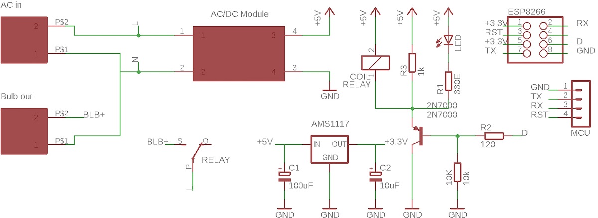
Is this the schematic you are referring to?
Thanks.
Yes. That's the one!
regards
Hi again.
What is that MCU that is connected via serial?
Hi
That is the output of the ESP-01 for checking on the serial. Kindly ignore it.
Thanks
regards
Hi.
Can you please try the following:
- disconnect everything from the TX and RX pins
- exclude any Serial.print() from your code
Do you keep having the same problem?
Hi
Thanks for the reply.Yes have the same problem.
I could resolve the problem by pulling up GPIO2 with a 1k resistor. The Blue LED does not glow now and the ESP-01 goes into AP mode and I am able to connect. However, the relay is ON by doing this. As a result, it is now working in reverse which is not desired. Any suggestions?
Please advise how to resolve now.
Thanks
Hi.
I think that depends if your relay is normally closed or normally open.
I don't know if there is another way to solve this, but if it is working in reverse, switch the HIGH with LOW in the code.
Hi
Sorry not so good at coding. Could you please highlight where i should change?
Thanks
You just need to switch the HIGH with LOW.
For example,
digitalWrite(atoi(output), LOW);
is replaced by
digitalWrite(atoi(output), HIGH);
and the following
digitalWrite(atoi(output), HIGH);
is replaced by
digitalWrite(atoi(output), LOW);
It is as simple as this.
I hope it helps.
Regards,
Sara
Hi
Thanks for the input.
I changed the code as mentioned, still does not work.
The relay is always ON initially at the start. Everything else is working absolutely fine.
How can the relay be OFF at the start/boot?
Thanks
Make sure that you're setting your output to HIGH (so it stays LOW) at the setup():
pinMode(atoi(output), OUTPUT); // Set outputs to LOW digitalWrite(atoi(output), HIGH);;
Hi
Thanks for the reply. Following are the observations
- When "digitalWrite(atoi(output),HIGH);;" the relay is ON at start. Only when the webpage for switching is called that the relay switches OFF.
- When "digitalWrite(atoi(output),LOW);;" the relay is ON at start. But as soon as it connects to local WiFi, it switches off and works normally.
The problem still remains unresolved. Kindly advise as the requirement is that Relay should always be OFF till it is switched thru the webpage.
Thanks
Regards
Hi again.
Honestly, I don't know where to go from here. What may be happening is that the ESP-01 uses that pin for a few seconds when it boots and the relay is activated for a few seconds. However, as soon as you send the command to switch it off, it should be turned off, without the need to go to the web page.
I don't know what could be happening and it is very difficult to understand what may be the problem. Sorry that I can't help much without further information.
You can try simplifying your circuit using a 3.3V relay module like this one and see if the problem is solved: https://makeradvisor.com/tools/1-channel-3v-relay-module/
Regards,
Sara
Hi
Thanks for the reply. Thanks for the help. Appreciate it.
I tried with couple of ESP-01 and both giving the same result.
I am thinking of changing to ESP-12e or any other ESP with more GPIOs to resolve this issue.
Does that make sense?
Thanks a lot
regards
Yes. The ESP-01 is very limited in terms of GPIOs.
Using other ESP with more GPIOs will be more versatile and you can experiment with other pins.
Regards,
Sara
Thank you so much. Will try this and reply.
Regards
Amit
Hi,
Your tutorials are excellent and very thorough. Thanks a lot!!. You guys are doing tremendous work helping people . Keep up the great work.
Based on your suggestions I tried using ESP-12e for the same project and it worked well on the breadboard. Thanks!!
As you mentioned that there are more pis to experiment, I thought of adding IR remote to the project. I found that sometimes when the home wifi will not be available then the IR remote would help. I am able to use the IR remote to control the relay independently. Thanks again to your tutorial on IR remote. Now I want combine the 2 such that incase wifi is not available, the device can still be controlled by IR remote. Any suggestions for coding?
Thanks Once again.
Best
Hi
Further to above, I also plan to add measurement of Energy consumption of the connected device which is controlled by relay. I am planning to use ACS712 for current measurement and measure the power. I didn't find in any of your projects.
Possible to help?
Best
Unfortunately, we don't have any tutorials on that exact subject. We don't have more IR remote examples with the ESP8266.
I've never used the ACS712 module. But, it should be as simple as reading an analog value.
I can only help you if you have trouble following one of our code examples or projects. It is very hard for us to test or write custom project requests that we receive every day.
Sorry that I can't help much.
If you have any more doubts or questions, open a new question in the forum.
Regards,
Sara
Hi
Thanks for the reply.
The IR code in the tutorial was very helpful.
Understand that you guys must be super busy helping so many people.
Thanks so much for help in resolving the issues.
Will ask help in case I face difficulty in ACS712 code.
Thanks once again
Best
Thank you for understanding.
I'll close this question.
If you have any more questions, just open a new question in our forum.
Regards,
Sara
Source: https://rntlab.com/question/blue-led-of-esp8266-esp-01-keeps-glowing-continuously/
0 Response to "Esp 8266 Blue Led Esp 8266 Blue Led Gpio2"
Enregistrer un commentaire